


ERASMUS+ lectures in Foggia
Lecture-workshops at Conservatorio di musica Umberto Giordano, Italy - facets of electroacoustic music.

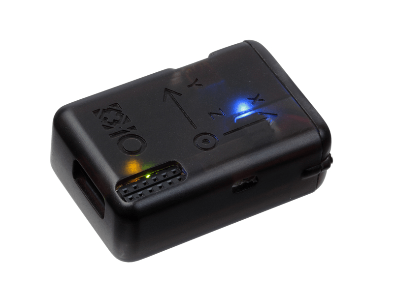
VIBRA has purchased four next generation IMU sensors from the British company X-IO. This type of sensor is a sequel to the X-OSC sensor, which has become quite popular because it uses the Open Sound Control (OSC) protocol, easily connects to the computer through Wi-Fi and includes both built-in accelerometer, gyroscope and magnetometer, as well as 32 analogue / digital channels where you can connect other sensors or actuators. For example, X-OSC is used in the mi.mu gloves and in Hilmar Thordarson’s ConDis conductor’s gloves for control of electronics for mixed music. With NGIMU, we got all this as well as a built-in algorithm for absolute orientation in a single package that is placed in a small box of hard plastic that also makes it less vulnerable than X-OSC (see the image at the top).
NGIMU is very easy to set up to get data from, especially if you only use a single sensor. When you turn it on, you will see that it appears on your computer as a wireless network. When you connect to this network, you already receive sensor data, but in order to use these, you must set up an OSC receiver in a program such as Csound, Max, Processing, PD or similar, and then with the correct port number and address (initial setting for port is 8000). X-IO has also provided software examples for various platforms and programming languages on their webpages. The manual provides an easy-to-understand overview of which sensor data is available at which addresses. So far in the VIBRA project, we have focused on orientation data as well as accelerometer and gyroscope data to get a value for overall “intensity” or “activity” regardless of the direction of motion. In this blog post we will primarily focus on absolute orientation expressed as euler angles (which are sent over the OSC-address /euler). It is also interesting that the sensor can send values for acceleration with gravity less and so-called quaternions. We hope to explore this in a future post.
Different settings can be applied to the sensor, including changing the port number, changing the measurement frequency (max 400 Hz) and selecting which values are sent over the network. This is done in a separate configuration program located on the X-IO website: http://x-io.co.uk/ngimu/ under «Downloads». The program is currently available only for Windows, which is obviously quite inconvenient for Mac users. On Windows, however, the program seems easy to use, and has a convenient visualization feature that provides a real-time animation of the sensor, clearly identifying whether the orientation data matches the reality (see video 1).
Video 1: Pitch, roll and yaw values (left to right)
NGIMU thus has a built-in algorithm to calculate absolute orientation, i.e. how the sensor is oriented relative to the directions in a three-dimensional space (x, y, z) available in so-called euler angles or quaternions. This algorithm does not need any calibration, and seems relatively robust, although it also has some of the problems associated with the so-called “gimbal lock”, something we will return to below. Previously, we used Adafruit BNO055 with an X-bee wireless connection to get similar data, but this required both calibration and some encoding to get the data sent over OSC.
While the setup with the BNO55 and X-bee had a rather noticeable delay, the response time of NGIMU is relatively low. A measurement of response time from a dunk on the sensor, via transmission over OSC to Csound, until it comes out as a small button is only around 18 ms. This allows you to play rhythmically on the sensor. Average response time over 10 measurements was 17.6ms with a standard deviation of 3.8ms. The measurement was performed by recording the sound from a knock on the sensor, which lay on a flat, stable surface. This knock will create a bump in the sensor measurement - we used the z-axis value of the accelerometer - and this measurement is recorded via OSC and converted to an audio signal written to the same file as the sound from the knock. By looking at the time difference between the two impulse sounds in this audio file, one will get a value for response time.
(NOTE! I have later found out that with Maximise throughput settings to “False”, one can get latency further down.)
Euler angles are angular values measured in degrees that indicate how the sensor is oriented relative to the directions of the sky, the gravity axis and its axis, and in three dimensions often referred to as yaw, pitch and roll - or rotation around the longitudinal direction of the sensor, horizontal slope (flat = > x = 0 deg) / rotation around the width of the sensor (flat => y = 0 deg) and horizontal direction (north = 0 deg). Video 1 above shows the values in Max.
However, there are some challenges with the euler angles. When the Y axis approaches +/- 90 deg, one approaches two-axis coincidence. This is usually called a “gimbal lock” in mathematics and engineering, causing major errors in the measurements. This is clearly seen in video 2 Gimbal lock, which by the way shows NGIMU’s configuration / viewer.
Video 2: Gimbal lock with Euler angles on NGIMU sensors.
Another challenge is that the rotation in the different axes will cross abruptly from the maximum value (eg +180 deg) to the minimum value (-180 o) in the opposite direction. Thus, one will get a big jump in values. This becomes particularly clear if you use this data to control the frequency of an oscillator. However, you can do a little trick to avoid such a jump by saying that you add or subtract 360 if such a jump occurs. If you know that you will not rotate several times in the same direction (which will give very high or very low values), this is at least a solution that can work. In video 3, Jumps in values (above), you can see my VIBRA / NTNU colleague Sigurd Saue who demonstrates this.
Lecture-workshops at Conservatorio di musica Umberto Giordano, Italy - facets of electroacoustic music.
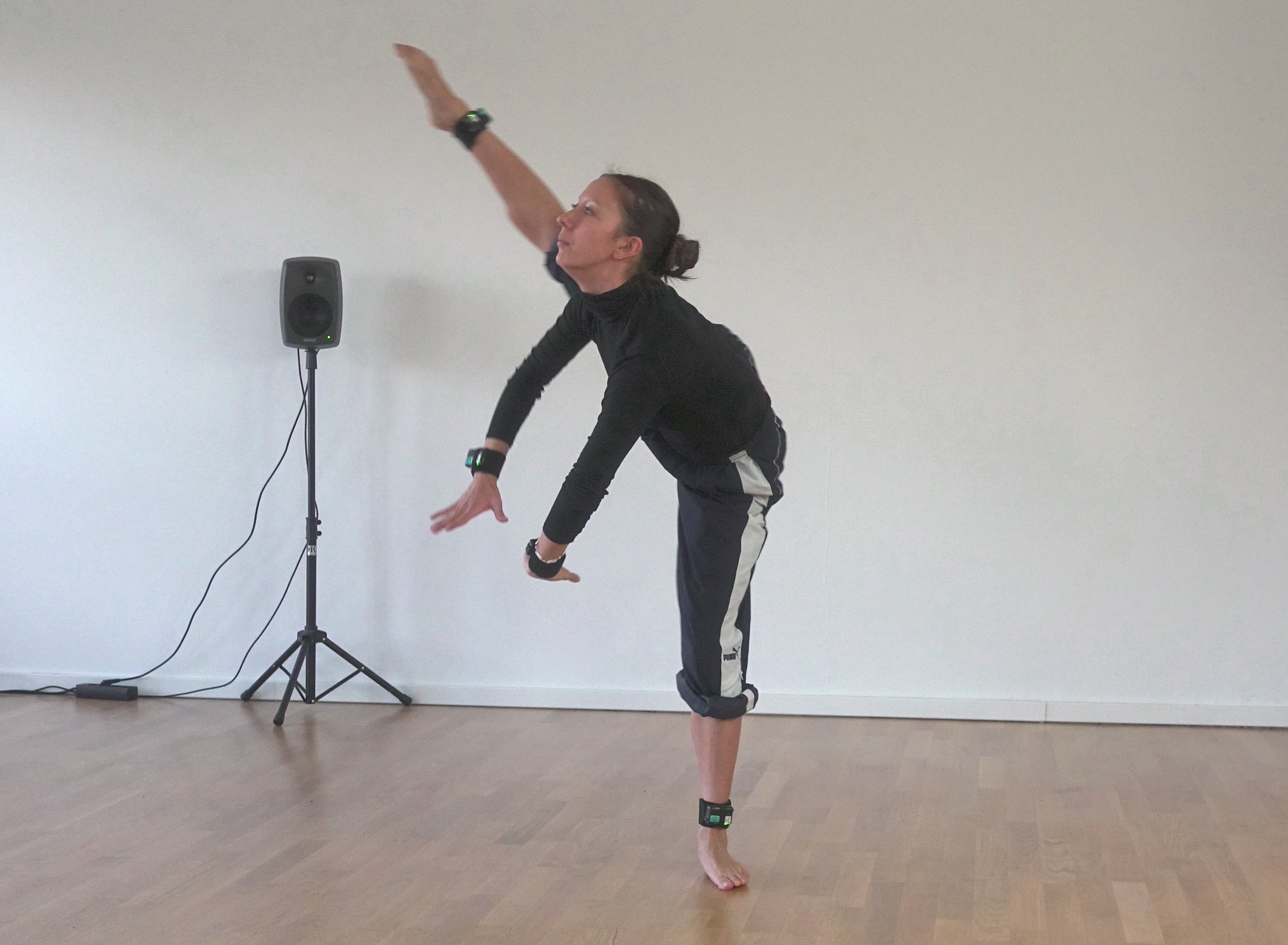
New interactive dance collaboration with dancer Camille Jackson and choreographer Robert Wechsler
Contributing to interactive sound-making objects in an art exhibition by Bella da Silva
